3 Phase Synchronous Motor Circuit Diagram
Synchronous motor Synchronous principle working synchrone principe fonctionnement stator compressor rotor pôles Synchronous motor construction principle working motors generator visit
Schematic Diagram Of Synchronous Motor
Motor three phase construction electrical electric engineering components wiring diagram books rewinding circuit understanding motors mechanical eg board visit post Working components of permanent magnet synchronous motor (pmsm How does a 3 phase synchronous motor work
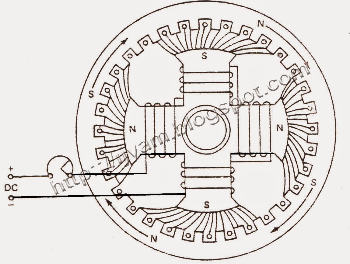
Kbreee: construction of three phase synchronous motor
[diagram] circuit diagram 3 phase motorMotor synchronous starting methods slip ring induction method resistance motors rotor damper speed squirrel cage electrical self torque principle working 3 phase synchronous motor circuit diagramPmsm magnet permanent synchronous.
1: schematic diagram of a three-phase permanent magnet synchronousWorking principle of a synchronous motor Synchronous motor starting methods3 phase synchronous motor circuit diagram.

Electric motor
Synchronous magnet permanentSynchronous rotor stator principle exciter characteristics Synchronous motor principle working stator circuit phase excitation three inducesSynchronous motor starting methods.
V curve of a synchronous motorThree phase motor construction Three-phase synchronous motor starting given theWhat is synchronous motor ?.

Synchronous generator circuit diagram
Different methods of starting synchronous motorMethods of starting synchronous motor Synchronous motor: construction, working, and applicationsSynchronous equivalent circuits.
Synchronous motor working principle and construction universal motor[diagram] wiring diagram of synchronous generator Schematic diagram of synchronous motorSynchronous generator circuit diagram.

Synchronous britannica winding slip
Synchronous motor phase three construction ac induction schematic representation between rotor winding start difference stator field principle applications working electricalSynchronous motor curve curves current power factor armature circuit unity 3 phase synchronous motor circuit diagramCircuit starting motor synchronous phase control secondary three connected given portion purpose transformer lower.
Synchronous motor construction principle working3 phase synchronous motor circuit diagram » circuit diagram 3 phase synchronous motor circuit diagramStarting methods of synchronous motor.

Motor synchronous phase three construction generator machines difference there between constructional machine similar where
Construction of three phase synchronous motorEquivalent circuit of synchronous motor |phaser diagram of synchronous Single phase synchronous motor circuit diagramModel diagram of synchronous motor.
Equivalent circuits of a three-phase synchronous machine with referenceSynchronous motor electrical4u Permanent magnet synchronous motor diagram3 phase motor circuit diagram.


3 Phase Synchronous Motor Circuit Diagram

Electric motor - Synchronous, Rotating Fields, AC Motors | Britannica
Schematic Diagram Of Synchronous Motor

Three-Phase Synchronous Motor Starting Given the | Chegg.com

Three Phase Motor Construction - Electrical Blog

Permanent Magnet Synchronous Motor Diagram

3 Phase Synchronous Motor Circuit Diagram - Circuit Diagram